Last time,I confessed that I prefer the Atari character set over the Commodore 64’s. I mentioned that I may look into getting an eprom chip converter and make the change on the board. What I realized as I started doing a little research into it, was that I had almost all the stuff to build my own home-grown adapter. So I set out to build my own adapter to install an eprom in the U5 character rom socket. The adapter I found online would convert from a 28 pin eprom to the 24 pin rom socket on the C64. I have a bunch of 32 pin eproms that I had purchased to program the 64NIC+ cartridge I had purchased a while back. I also have an eprom programmer for the same purpose. So here’s everything I had and needed to do this project:
- What I have:
- Eprom – 27C020 (This is a 250k eprom which is overkill to replace a 4k rom chip, but go with what you have)
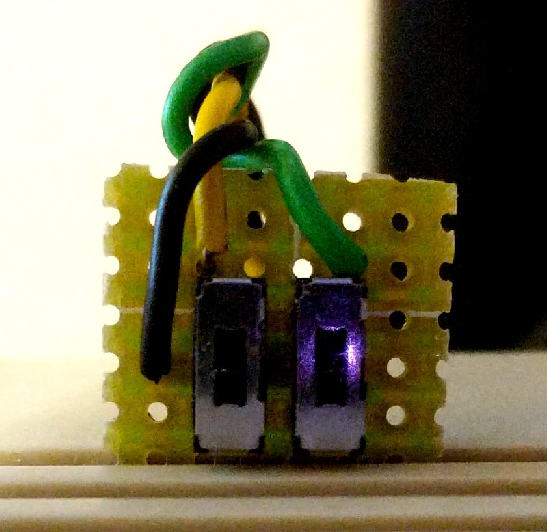
- 2 – PCB switches (Since I have so much space, I decided to make the font switchable. I set it to have 4 character sets)
- Prototyping perfboard (I like to mess with electronics so I have a few laying around)
- 24 pin & 32 pin IC socket. (I only had 40 pin, so I cut it to fit.
- Dip headers
- 20 AWG wire, various colors
- Soldering station, solder, misc tools
- What I needed (wanted) to get:
- Solder wick
- Solder sucker (my old one died)
- Solder rework station (Definitely a want, but great when working on pc boards.)
- 2 – 4.7k Ω resister (I ended up getting a kit because the cost was so low)
First Things First
Before I pulled out the soldering iron and opened up the C64, I needed to design the adapter. 64Copy Central has very helpful information for making adapters. There are two main differences between the C64 character ROM chip and the EPROM chip that I am using beyond the number of pins.
- The added addresses the EPROM has to access the 250k of data.
- The programming enable and VPP pins the EPROM needed for programming purposes.
I drew up the wiring diagram to the right, the blue area is the EPROM chip sitting on top of the yellow area which is the ROM chip. As you can see, many of the pins line up when you set the bottom of the chips together. Many people who make adapters will skip the perfboard altogether and mount one socket on another while diverting the different pins around with wire (I am not that skilled).
For the extra addresses, we will use 2 of the address pins to give us the added capacity for 4 total character sets. That will be pin 4 for address 12 and pin 28 for address 13. The pins will be connected to 4.7k Ω resisters going to VCC and switches going to ground. When the switch is open, it will feed voltage to the pin making it high (1). When the switch is closed it will ground out the pin making it low (0). This is bank switching the EPROM in 4k chunks. The rest of the extra address pins will be grounded low permanently and not be used.
VPP and P are programming pins. VPP is programming voltage and P is programming enable. VPP just wants to see voltage. The voltage needed to program an EPROM is higher than VCC so there is no danger of reprogramming the EPROM in the 64. Program enable is also connected to VCC because it reversed. The line over the P in the schematic means you need to set it low to enable it it. By setting it high we are telling the chip that it is not to be programmed.
The only other oddities are pins 22 and 24 on the EPROM and 21 on the ROM. On the EPROM, 22 is the chip enable pin and 24 is the output enable pin. They both go to pin 20 on the ROM which is chip enable 1 because the old ROM did not have separate chip and output enable pins.
Pin 21 on the ROM had me confused. As I read the datasheet, it looks like it has the ability to hold another 4k of data. It does not act like another address pin though because you could set both pins to high or low and the output would be OR’d together. I looked on the C64 schematic to see that pin 21 was simply set to high, since the EPROM does not have a second chip enable pin, I did not connect anything to pin 21 of the ROM.
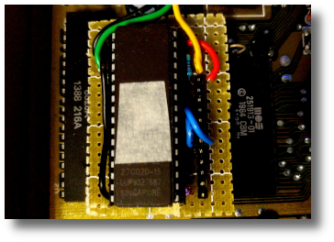
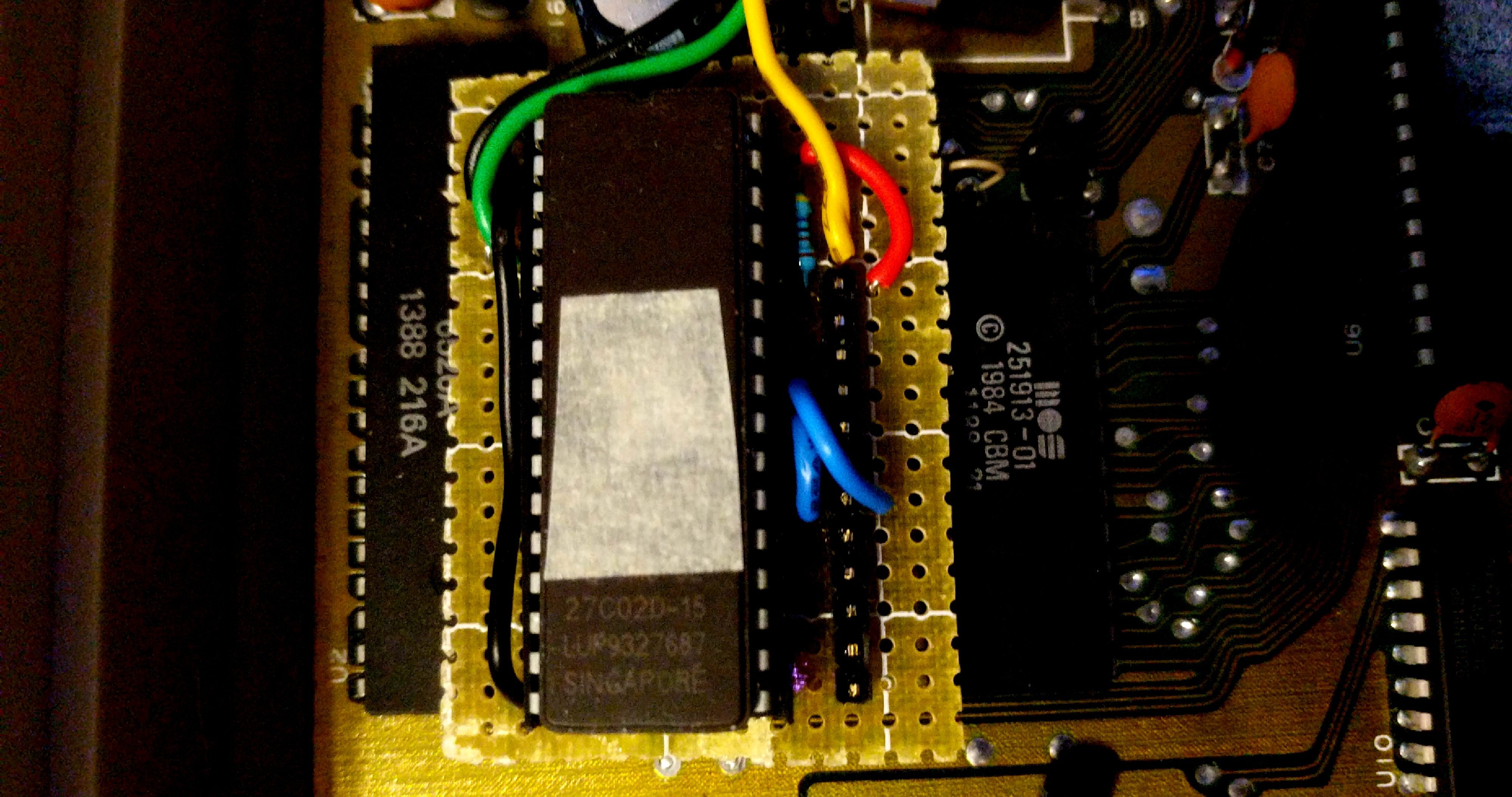
Soldering the board up was not too complicated. The dip headers went below the board to act like the chip going into the U5 socket. The 32 pin socket was lined up with the bottom of the headers and slightly offset to the left. Solder bridges were created to connect a majority of the pins to each other as specified by the drawing above. Some 20 gauge wire was used to connect the pins that didn’t line up. Red for VCC, black for ground and blue for data. Resistors were added as needed and then three long wires were added to go to the switches which are located outside the computer on another small perfboard.
Making the Character Sets
The next step was to build the character sets I was going to use. I initially planned to do this for the Atari set, but since the EPROM was more than 4k, I figured at the very minimum I would make it switchable between the C64 and the Atari sets. Since I had the switches, I decided to make 4 switchable sets. Adding a third switch would push it to 8 sets and I can’t imagine wanting to change things up that much. I had two character sets already in the can, the C64 set and the Atari set. Which other two should I make? Luckily, after posting the last blog, a facebook user linked to an 8bit typography blog post. After reading the post and related posts, I decided on adding the TI-99/4A set and the Amstrad CPC set. They are both unique to the two I had already decided to use. The TI-99/4A, specifically because the lower case letters are just really short upper case letters and the Amstrad CPC tried to make a serif (fancy) set to mimic some of the other business machines out there.
To make sure I was making the sets accurately, I grabbed the image of the sets, blew them up and drew a grid over them using Gimp. I them proceeded to create them using CBM prg Studio. Once the characters were programmed, I exported the entire set to an assembly listing in CBM prg Studio as BYTE information, gave the data a starting address of $3000 and checked the resulting files in VICE. Once the program was loaded into VICE, a POKE 53272,29 let me see the new character set on the screen. The great thing is that the prg file that CBM prg Studio creates can also be used for the EPROM programmer. Which leads me to…
Programming the EPROM

Now I have my 4 character sets created, I need to get them on the EPROM sequentially. I have 4 separate files with the data. First things first, I make sure the EPROM is blank. These are UV erasable, so I stick a few in the UV erasing box for 30 minutes to clean them out. Once they are done, I do a blank check with the programmer to ensure it is ready to go.
Loading the files into the programmer is simple. Once the type of chip is selected and checked to be blank, I start loading character sets. I started with the C64 set first. When a new file is chosen, the software asks where I want to start reading data from the file and where I want to put the data on the EPROM. For the C64 set, I leave the data start at 0 for both the file and EPROM. This will put the data at the beginning of the EPROM. The data will take addressess $0000 to $0FFF on the chip (decimal 0 to 4095).
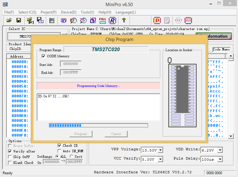
Adding the next 3 files is just slightly different. Once the file is selected, you need to tell the programmer to ignore the first two bytes of the prg file. Those first two bytes are the memory location where the program is to be loaded in the C64. Since we don’t need that information, we tell the eprom programmer to start reading the file at byte 2. The next thing to modify is where to start putting the data on the EPROM. The second set starts at $1000, the third at $2000 and the forth at $3000. The clear buffer option also needs to be disabled so the programmer doesn’t clear out the other files we loaded up. Finally hit the program button and let it go!
Installation
The last thing to do is pull the old character ROM out and install the new EPROM with the adapter. I did this first on my Frankenstein breadbin C64 that I own. This 64 had some major issues when I got it and I have managed to get it “mostly” working. There is an issue when I use svideo for display that is not there when I simply use composite out, so it is not a priority right now, I use my 64C as my primary machine. Because of this, the breadbin is the “test subject”.
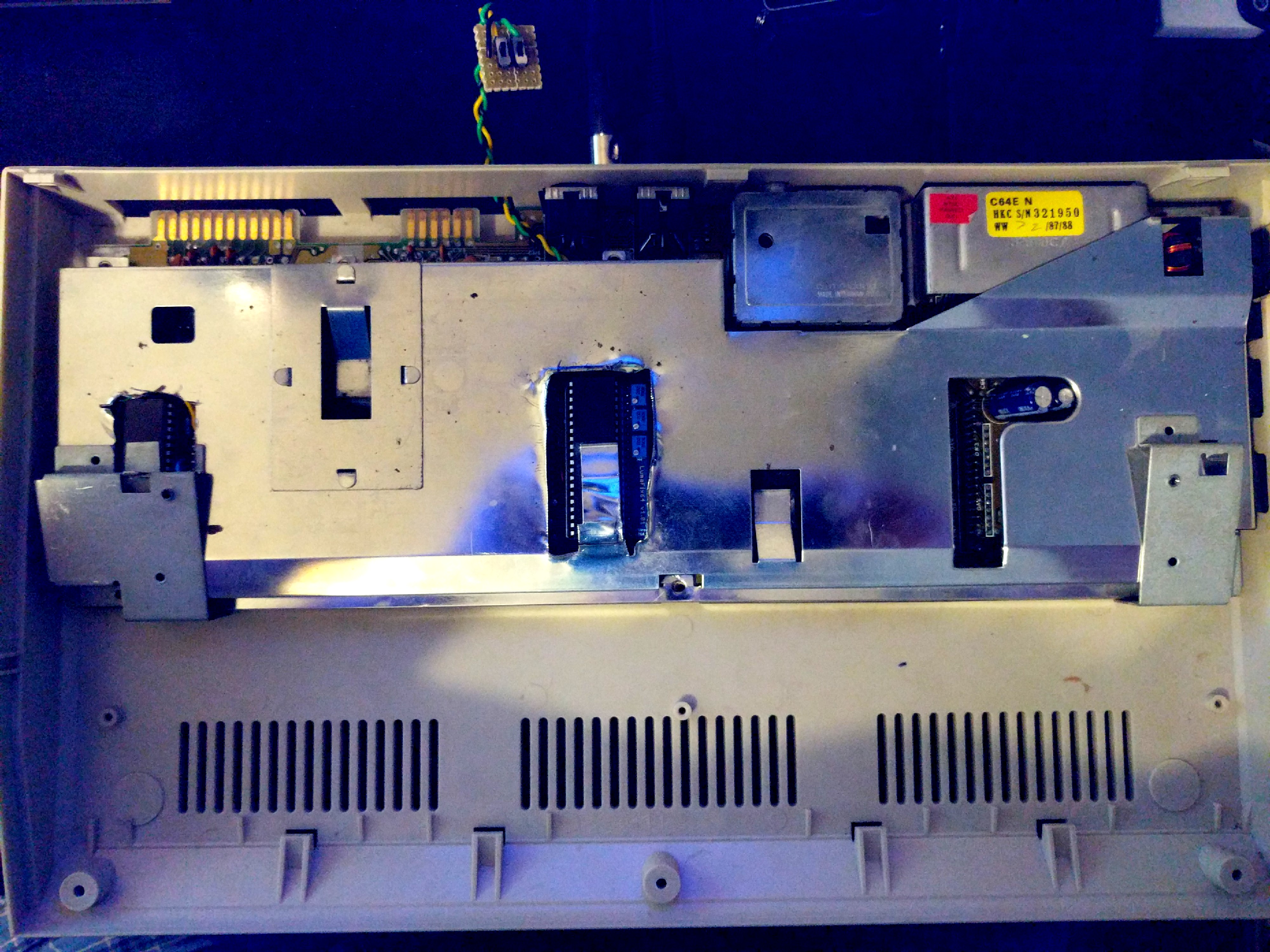
First thing is pulling the old ROM. This is where the air rework station came in handy. I was able to clean all the solder out and pull the ROM out cleanly. I then installed a new socket onto the board and inserted the adapter into the chip. I plugged it in and powered it up. SUCCESS! I had four character sets available at my fingertips. I was also able to switch from one to the other while the computer was on since I’m only changing the address of the bank that the C64 sees for character definitions. I let the machine run for a while waiting for flames to shoot out of it, but there were no issues at all. I shut down, swapped the adapter out with the original ROM and checked to make sure it was still working (it was) and closed it up.
The next step was to get it installed in my 64C. Things went just as smoothly for that machine, except, the height of the new chip and adapter interfered with the metal RF cover/heat shield. I took out the tin snips and dremel to quickly cut a hole in the shield. I had cut a hole in it in the past to accommodate the Lumifix64 I installed after changing my output from composite to svideo. I’ll probably go back and clean up both holes in the future. I was too excited to get the machine up and running again to finish it right then. I plugged it in and checked it out. All 4 sets are available to me. I let it burn in for a while to be sure there were no issues before I put the 64 back together. Finally, I ran the 2 switches through the hole of the cassette drive connector since I haven’t used it for some time and placed the switch board in the “grill” on the top of the 64. I didn’t want to drill any holes in the case, at least not with the prototype board.
Post Mortem
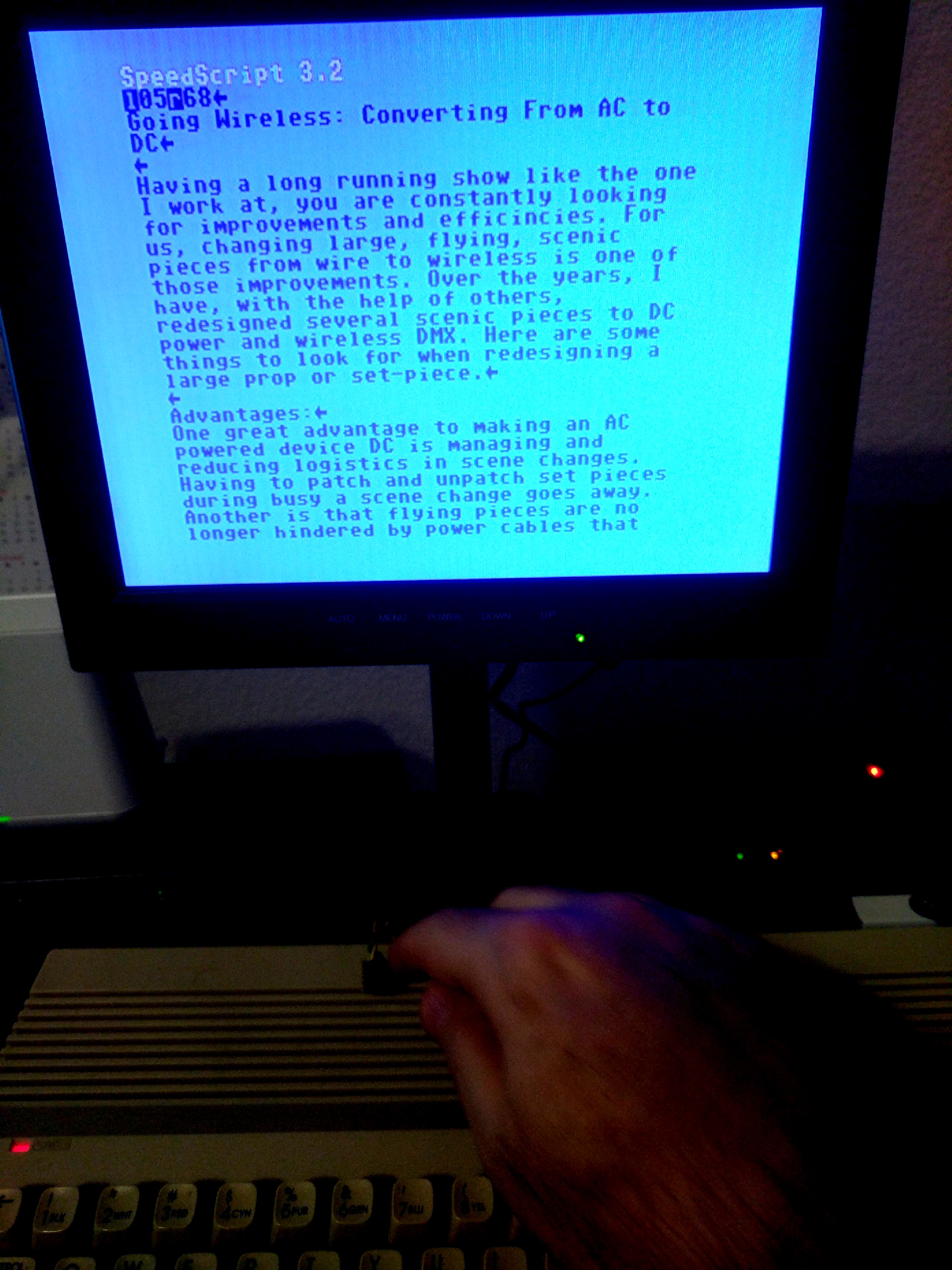
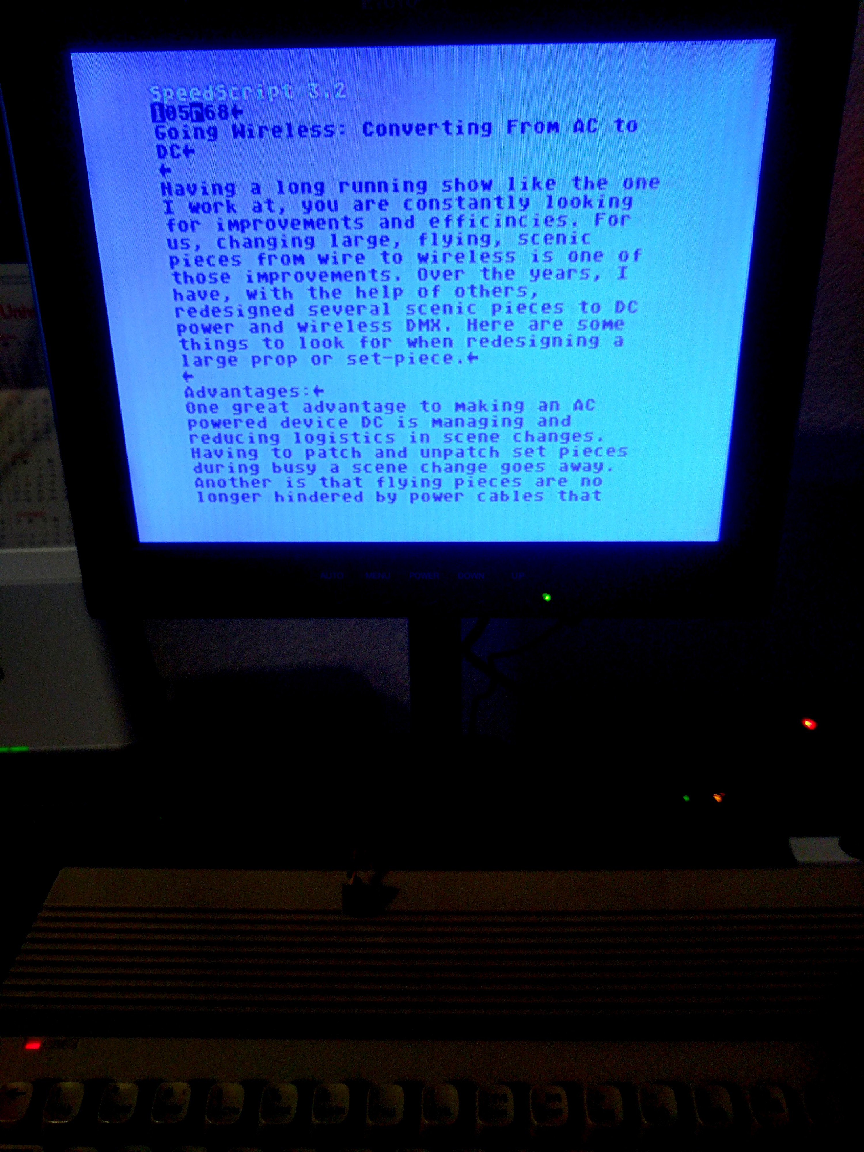
I tend to keep the characters set to the Atari letters because I do like them better. I do find that I like the TI-99/4A set when I’m going online with it. I haven’t really found a good place to use the Amstrad CPC set yet, although it looks ok when I use Speedscript. It could be the set I change every now and then to see something new.
In the future, I might design a board to be manufactured to make the install much cleaner. I would have two made so I can put them in both computers. It was a fun project that got me off track on my programming A.I. project. Time to get back to it!
c
Perhaps you could attach each of the font files to this post, c-64.ttf, atari.ttf, ti994a,ttf, amstradCPC.ttf