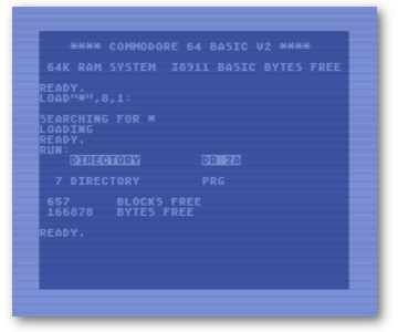
Download: l-system.d64 image
So my continued dive down the rabbit hole of fractals has led me to discover L-Systems. To quote Wikipedia:
An L-system or Lindenmayer system is a parallelrewriting system and a type of formal grammar. An L-system consists of an alphabet of symbols that can be used to make strings, a collection of production rules that expand each symbol into some larger string of symbols, an initial “axiom” string from which to begin construction, and a mechanism for translating the generated strings into geometric structures.
https://en.wikipedia.org/wiki/L-system
L-Systems were originally created in 1968 to help describe the behavior of plant cells and their process of growth. Using them can create realistic models of virtual plant life. They can also be used to generate repetitive pattern fractals on the computer. A thing I am very much interested in!
So what is this parallel writing system and formal grammar Wikipedia is talking about? Here is simple example of how L-Systems work. First, there is an Alphabet. These are a set a characters that have a specific meaning. Some characters can be replaced, making them variables, and others cannot, making them constants. A simple example (which we will use in our BASIC Program) is “F”, “+”, and “-“. “F” represents a variable that can be replaced and means to move forward a set amount. Think of Turtle Graphics where a Forward command would move the cursor forward which ever direction it was facing on the screen. “F” can be replaced by another character, or multiple characters. “+” and “-” are constants and cannot be altered. “+” represents rotating the cursor right a certain number of degrees and “-” represents rotating the cursor left a certain amount of degrees. For our system, we will add another variable, called “G”, which also move the cursor forward, but will have different rules attached to it.
Next we need a starting point, written as a string. So for our first L-System example, our starting string will be:
F + F + F + FWhat this tells the system is that our initial state indicates that we will move forward, turn right, move forward, turn right, move forward, turn right, and move forward. If the set amount to move was 1 and the angle to turn was 90, this command would create a square 1×1. For the C64 however, I had two lengths, X=319 and Y=199. This will create a box the full resolution of the C64 hi-res screen. This brings us to final ingredient for our L-system, the rules. Production rules define how variables get replaced. For this program the rule is:
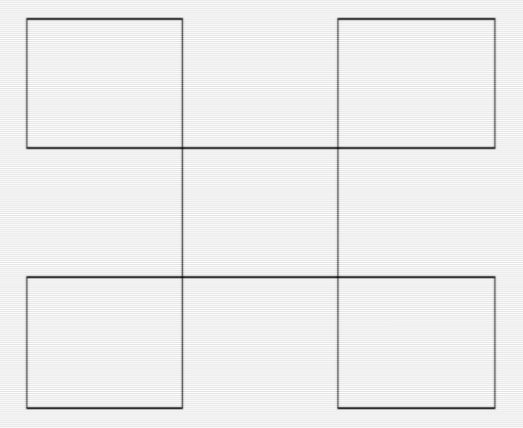
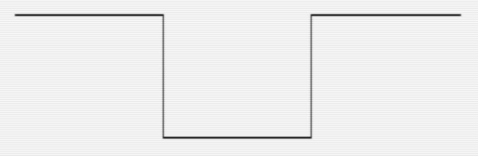
F → F + F - F - F + FHere, every time “F” is encountered in the string it is replaced with “F+F-F-F+F”. We know that “F” represents a single movement forward a set length. What does this new series of characters we just replaced “F” with look like? You can draw it out on graph paper and follow the rules yourself. If you do, you should come up with the following image:

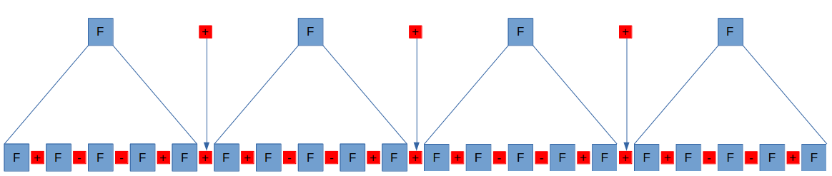
On the first pass through the L-system with the rule listed above, “F+F+F+F” becomes “F+F-F-F+F+F+F-F-F+F+F+F-F-F+F+F+F-F-F+F”. The diagram below shows what’s happening.
The image this string would create looks like this:
On the second pass, every “F” again will be replaced with the string of “F + F – F – F + F”. The next image would look like this:
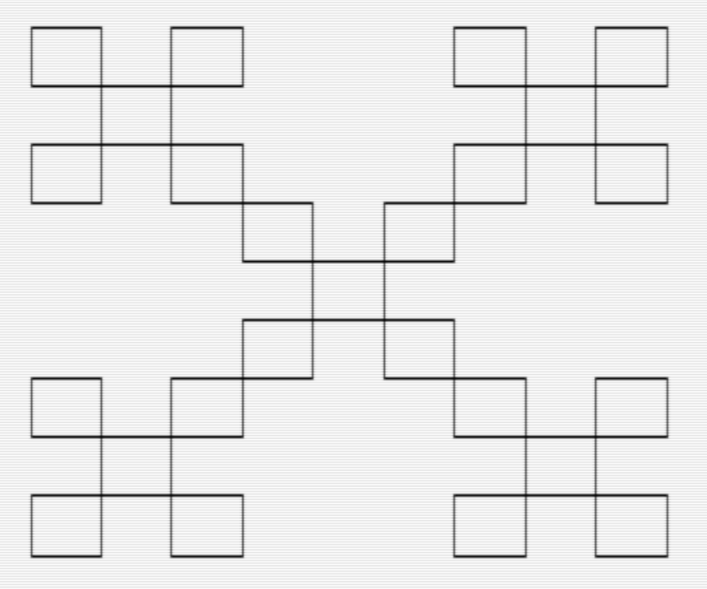
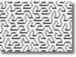
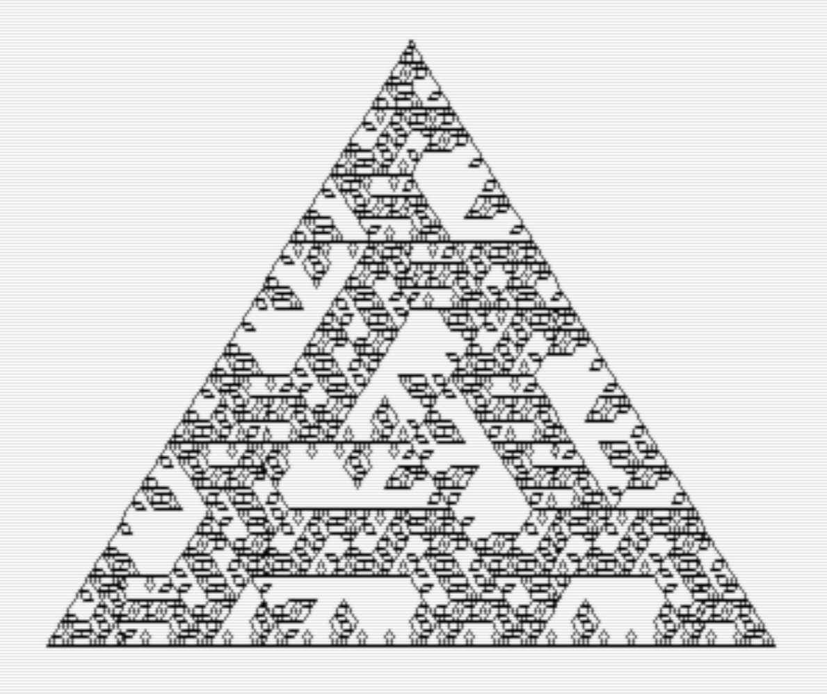
Every pass will make the image more complex even though it is built on the same simple building blocks. After four passes, the fractal will look like this (you can watch your 64 draw this by running the program “KOCH VARIATION” on the .d64 image):
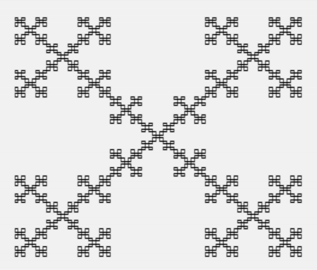
Needless to say, taking a single character from a string and replacing it with 9 causes your string to expand exponentially. The original string had 7 characters, after the first pass the string had 39 characters. After the second pass it was 199 characters, and after the forth pass making the image above, it was 5049 characters. This means that although the program to generate these images is relatively simple, they become very memory hungry with each pass adding complexity. In our program, every character of the string takes one byte making this image consume 5k of memory for the 4th pass.
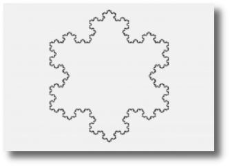
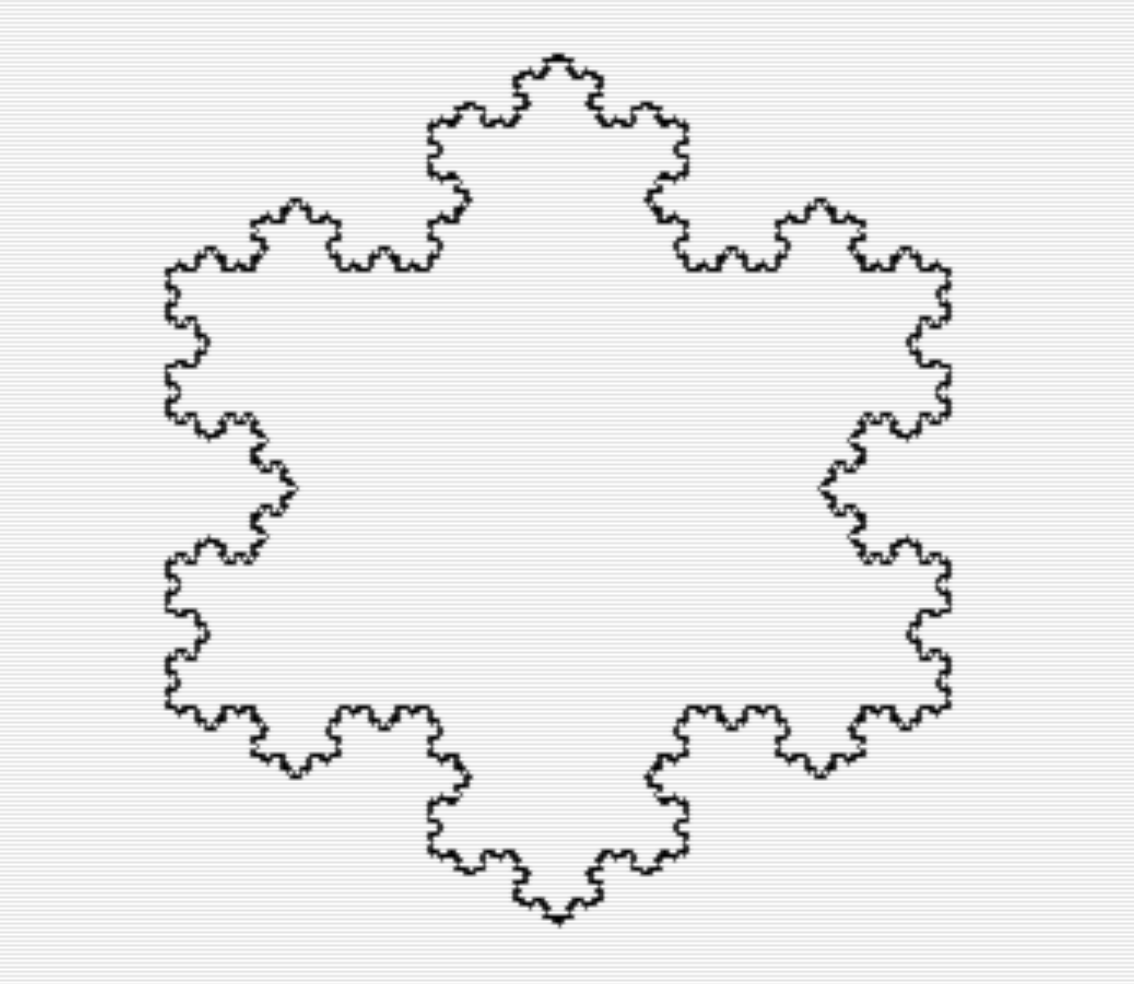
This particular fractal generated is a variant of the Koch Curve using only right angles as described in the Wikipedia article quoted above. You can also generate the more common Koch Curve (or Snowflake) by changing the turning angle from 90 to 60 and changing the rules a bit. Below is the Koch snowflake. You can have the 64 draw this by running the “KOCH SNOWFLAKE” file in the .d64 image.
Sierpinski’s Triangle Revisited.
In my previous post, I found a way to create Sierpinski’s triangle using a method that didn’t involve recursion. While investigating L-systems, I discovered another, although this method takes up a bit more memory. It is also the reason I added the second rule in our BASIC L-system (“SIERPINSKI TRI” on the .64 image“).
Here are the rules for this drawing:
Turn Angle = 120
Initial String = "F + G + G"
Rules:
F → F + G - F - G + F
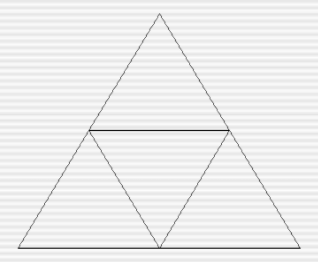
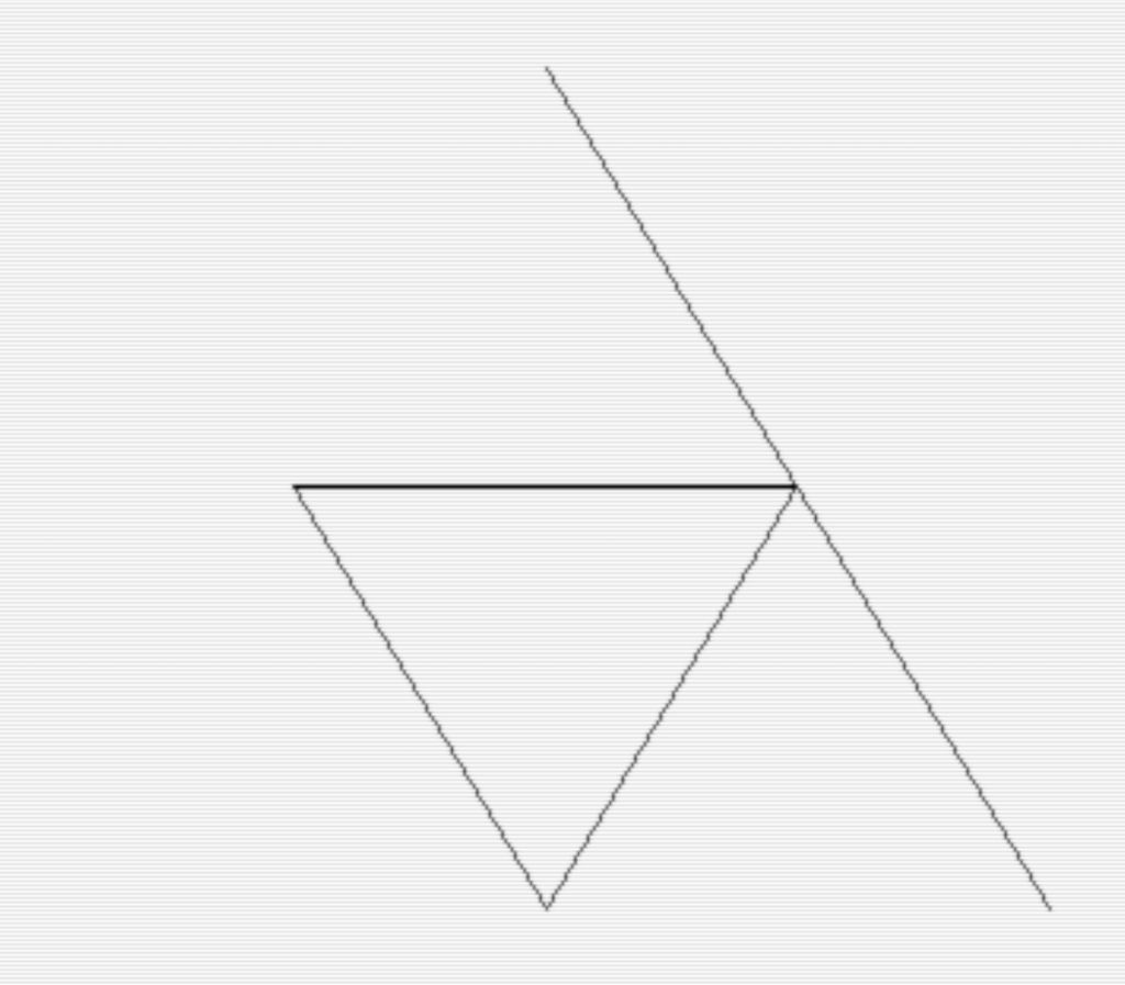
G → G G When you break down a single “F” rule you get the following shape (note: I started this shape from the center top position and had a starting angle of 60 degrees):

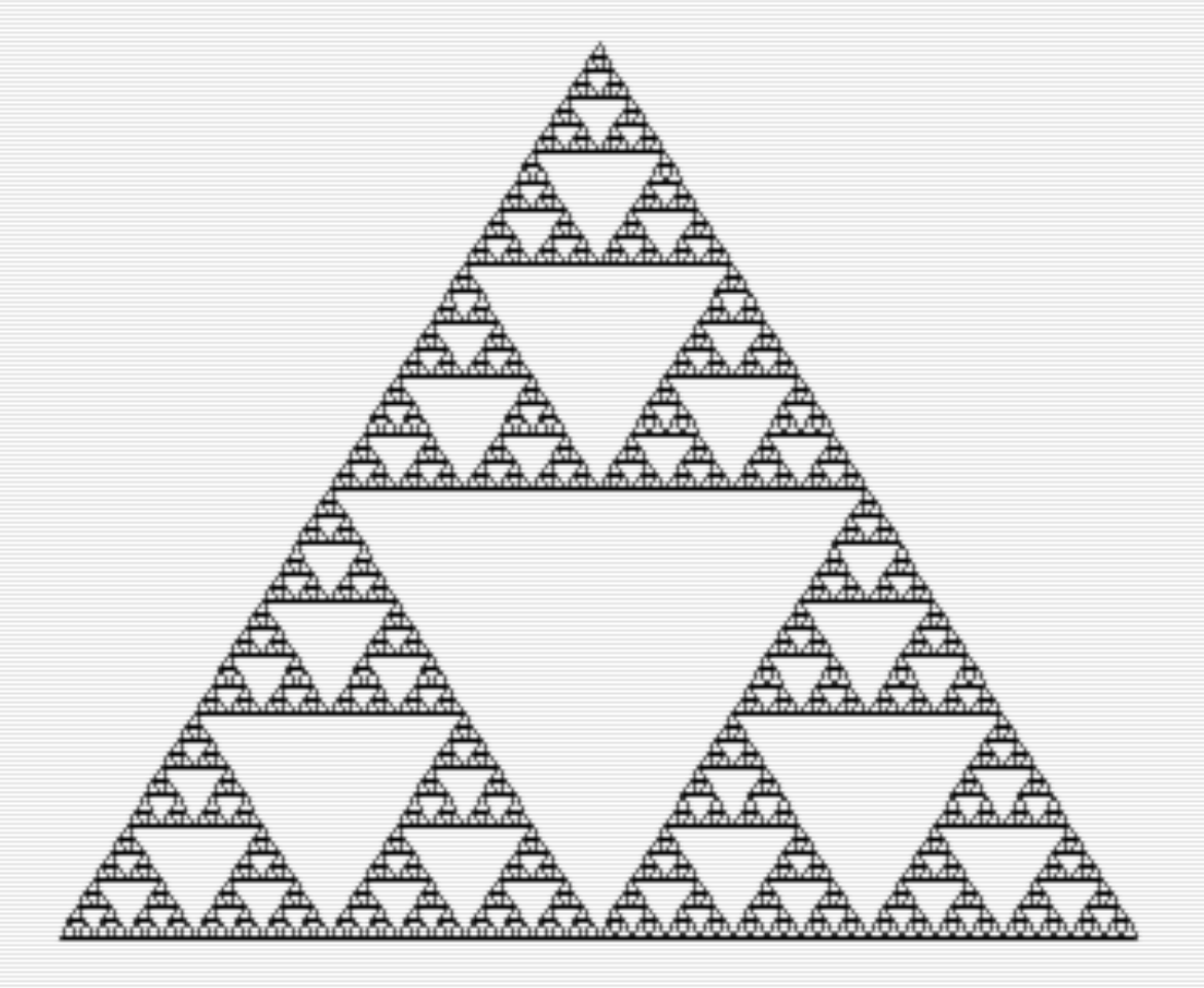
When you add the second rule to the first pass, you get “F+G-F-G+F+GG+GG” which draws the line on the bottom, turns right 120 degrees and draw the angled line back up to close the triangle.
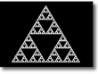
Simply adding more passes to this set of rules will continue to add more triangles within the structure building Sierpinski’s Triangle quite quickly. After playing with the program for a while you can start to appreciate how simple, yet powerful it is for generating interesting and unique fractals.
Make Your Own Rules!
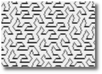
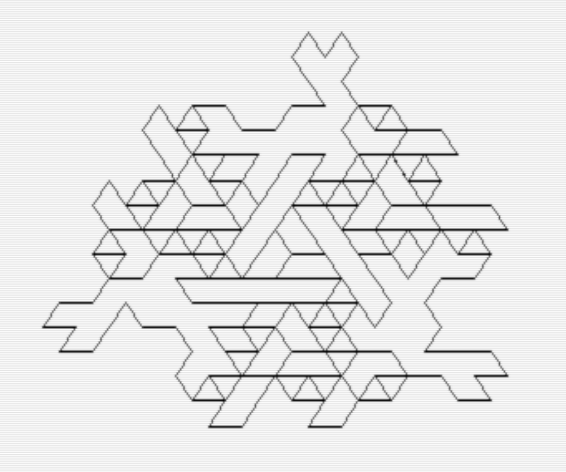
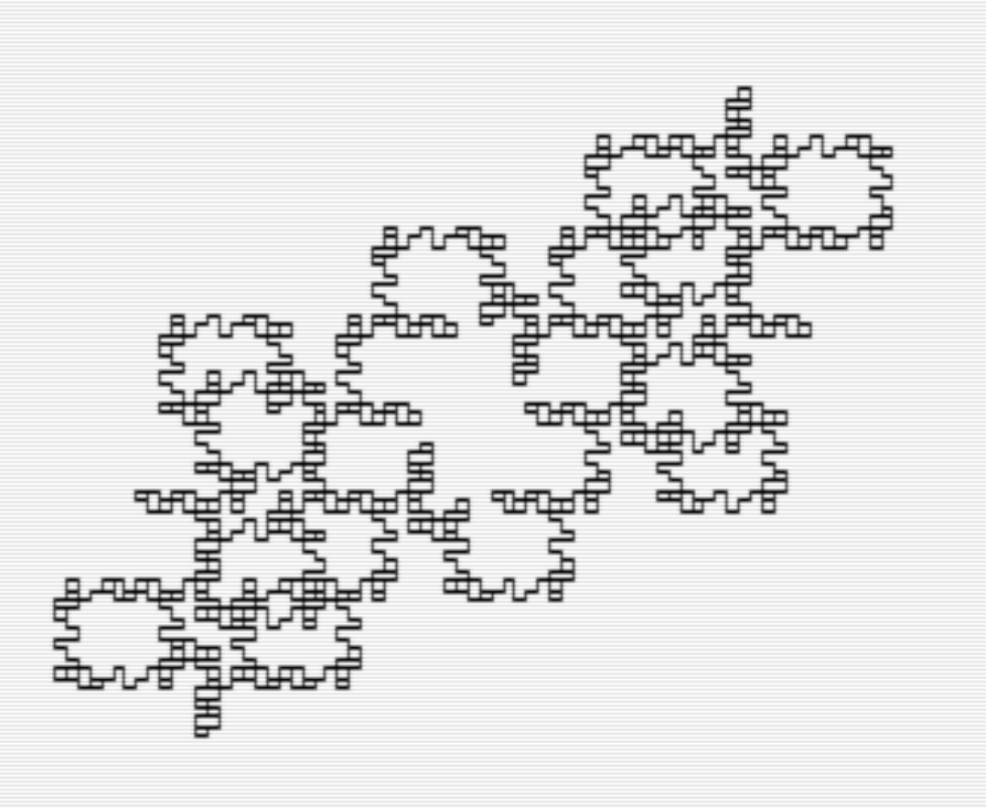
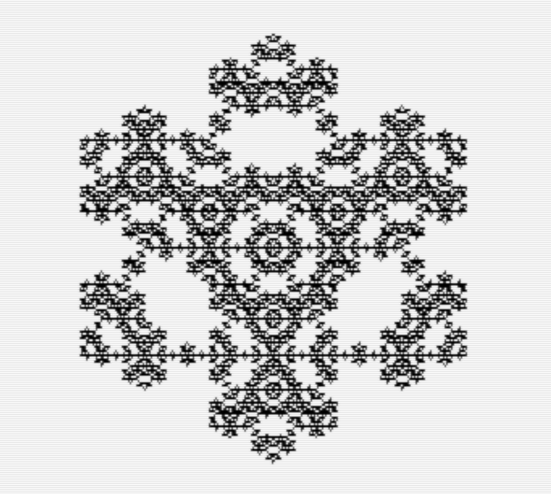
I hope this gives you an understanding on how L-systems to because knowing how they work will help you experiment and create your own rules to try out. On the .d64 image there is a file called “LSYSTEM TEMPLATE” that was used to create all of these images by altering a few variables. I’ve been having some fun playing with different rules and trying to come up with interesting shapes. Here are some of the images I created by making up some rules. I’ve found that it helps to graph out your rule and end the rule in the same direction that it started. That is not a hard and fast rule, however, and many interesting images can be created by breaking that rule.
Altering the Template
As mentioned above, all these images were created using the same template and altering some variables. I’ve tried to make it as easy as possible for you to alter the program. If you do a LIST 1090-1270, everything that needs to be adjusted for a new image should fit on the screen.
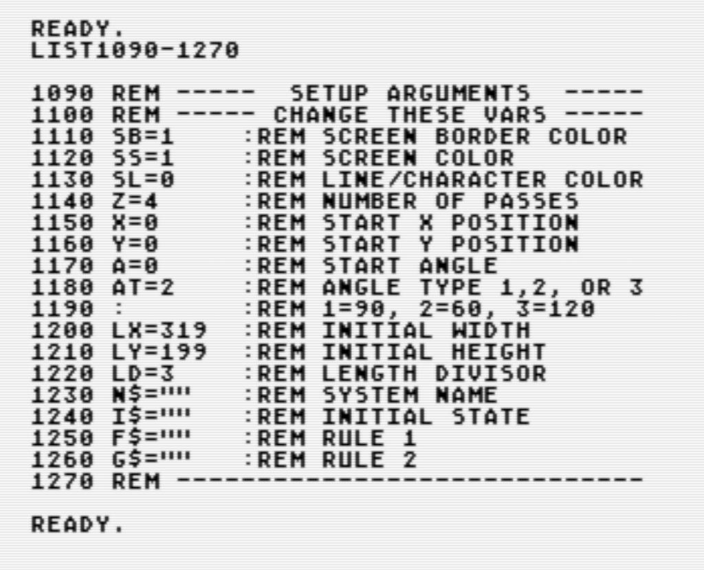
You can load any of the programs on the image and see how these parameters are set to create their images. You can also alter them and see what happens. Here is a breakdown of all the variables to create your own L-system image:
SB, SS, SL: These are variables for the border, screen and character/graphic colors of the screen. They use the standard C64 0-15 color codes. They are defaulted to white border/screen, black character/lines.
Z: This variable is the number of passes the L-system will go through to generate the image. A high number will increase the detail as well as consume more memory. There is 20K of memory reserved for stack space to generate images. There is room to increase this number, but most images should fit in this 20K of space (if you do get a stack overflow error, you can execute a GOTO 1920 command to see how much of your creation was drawn). It is recommended starting with a lower number when trying out new rules so that you get an idea of what’s getting drawn before you spend a lot of time generating the image.
X, Y: X and Y track where the “turtle” is during the drawing of the image. You can specify the starting point here. This is useful if your image goes off in a direction off the screen. You can also set this to X=160, Y=100 to start in the center of the screen when you’re not sure which direction your image may go.
A: This is your starting direction in degrees for your “turtle”. Zero is to the right. Increasing degrees go clockwise, so 90 degree would be going down on the screen. Negative numbers are not allowed. Also, this number needs to be a multiple of 90 when using the 90 degree turn angles or a multiple of 60 degrees when using the 60 or 120 degree turn angles.
AT: This is the angle type you plan to use in your rules. This effects how the “+” and “-” characters are interpreted. There are three options for AT, 1 for 90 degree turns, 2 for 60 degree turns, and 3 for 120 degree turns. Other values will eventually give you an error in the program.
LX, LY: These represent the initial length of of lines drawn on initial string. For example, If your initial string simply had a “F” the line would be drawn this initial length. These variables default to 319,199. You may need to reduce these numbers if your image expands outside the size of the screen. I usually like to reduce them by multiplying them by a percentage decimal. For example, on Koch’s Snowflake, the line length had to be reduced by multiplying both LX and LY by 0.75.
LD: LD is the Length Divisor. Every pass the L-system goes through LX and LY are divided by this number. To determine what this number should be, you need to look at your rules and see how your line gets divided up along the same angle. For example if your single “F” turns into “FF”, then your single line is twice as long and LD would need to be 2. If “F” becomes “FFF”, then your line is three times as long and needs to be divided by 3. Rules are never really this straight forward though. The first example in this article has an LD of 3 because the line is broken up into three pieces.
On the other hand, the Sierpinski Triangle example has an LD of 2 because the initial line is intersected in the middle to create the new triangle. So the line is broken in half. You can tell you need to adjust this number if your image is different sizes when you change the Z variable to change the number of passes you want to run your rules through.
N$: This is simply the name you want to call your image and is printed on the screen at the beginning of calculating the system.
I$: This is the initial string for your image. It is defined by the same characters you use in your rules. For example, if you turn angle is set to 90 degrees, “F++F” will draw a line, turn it around 180 degrees and draw it back. “F+F+F+F” will draw a square. With the turn angle set to 60 degrees, “F++F++F” will draw a triangle, “F+F+F+F+F+F” will draw a hexagon. And finally, with the turn angle set to 120, “F+F+F” will create a triangle.
F$: This is your Rule 1. If you are only making 1 rule, use F$ and not G$. The program always processes F$.
G$: This is your Rule 2. If you don’t have a second rule, simply leave this as is and the program will ignore it.
Conclusion
I really enjoyed this project. If you haven’t noticed, I enjoy getting the computer to draw stuff on it’s own. I especially like these L-systems because of how simple the programming was for it. Moving forward I have been thinking about building a machine language version of this where the user would be prompted for variable information instead of altering the program. Saving would then be just of the variable data and not the entire program. A machine language version of this would be much faster and probably free up more RAM for the stack.
I plan to follow up this article with another detailing the BASIC program itself and how it works. The listing is pretty well documented so I think many people will be able to figure out what I was thinking.
I hope you found this informative, please play and enjoy!
-M