My first computer
The VIC-20 was my first computer growing up. My parents got it for me after I took a summer class on computers. Those computers were Commodore PET machines. Obviously my folks saw something in my fascination with the computer (I was cutting other classes to hang out in the computer lab) that they thought they should encourage.
At the time, the VIC was new and the Commodore 64 wasn’t out yet. At the store they were saying that it would be out soon, but it was going to be $595. Being that they had VIC-20s now and the price was a little more manageable for my folks, we picked up the VIC-20.
I loved that machine growing up, and it was very capable except for the fact that it had so little ram. I ran out of memory pretty quickly programming in BASIC. Even after I had gotten the Super Expander (with it’s extra 3k of ram and more commands) I outgrew its capacity and longed for the Commodore 64.
I eventually got the C64 and don’t know what happened to the VIC after that. Until recently, I hadn’t thought much about the VIC nor did I have any plans to get one or play with one until one day.
That fateful day
I have a friend who buys and sells stuff, some may call it junk, other people call it treasure. My friend has been into books recently and I had mentioned if he came across any old computer books and especially commodore books that I would be interested. He came across a few in his travels, and recently, while looking at an estate sale, he came across a room full of vintage computers. Old Commodore machines, Ohio Research computers, computer chips scattered everywhere. Of those machines he showed me a photo of an old VIC-20 with the PET style keyboard and a beat up Commodore 128. I took both.
The VIC was in pretty good shape, but it was missing it’s voltage regulator inside the computer. It’s a rare item, as the motherboard was a 1001006 REV E board which used the Japanese SI-3354M regulator instead of the more common LMK323 regulators that more of the old VIC-20s had. It took a little while but I came up with a replacement that works and got the machine up running.
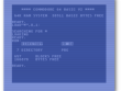
The old nostalgia buttons were on overload and I needed to do something with this computer. After a short amount of time it was obvious looking at the screen and its message, 3583 BYTES FREE. I knew right then I wanted to build RAM expansion for this machine.
After some thought and searching around on the internet I came up with a design. It is mostly the work of Ruud Baltissen that my upgrade cartridge is based on. It is this page that I stumbled across. He built a 27k+8k ram schematic to upgrade his VIC. He also favored adding the memory internally to the computer by piggy-backing to one of the ROM chips. I was thinking about going this route as well as his argument was that building the memory internally still allowed you to put in a cartridge if you wanted to.
I had started collecting the things I would need to put the memory internally into the computer, but as I thought about it, it seemed more complicated to do than to just build an actual cartridge. After all, the slot is made specifically for this purpose. As I continued to research, I also discovered that the +8 of RAM Ruud was adding to the computer would not be seen by BASIC because of its location on the memory map. That +8 of RAM is used normally as the slot for 4 and 8k ROM cartridges. I decided then that I would add an EPROM to my card and program it with whatever ROM I would like. It so happened that I had 27C020 EPROMS from another project. Those EPROMS can hold 256k of data, so with a little circuitry I could make 32 8k slots in a single card.
The Cartridge
Using what I had learned from Ruud’s web page as well as what I knew from using EPROMs in the past, and some other research regarding pull-up & pull-down resistors and capacitors for filtering power, I created the schematic below.
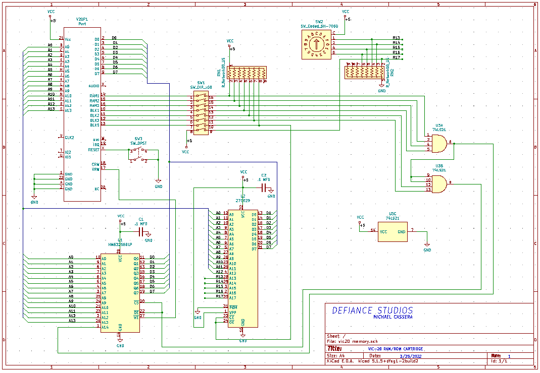
The whole circuit uses:
- 1) 8 channel dip switch to turn on and off the RAM/ROM and select between the first 16 slots or the last 16 slots of the EPROM chip.
- 1) binary coded 16 position rotary dial to select which 8k eprom slot you want in place at $a000
- 1) reset button to reset the VIC
- 2) 10k ohm, 9 pin resistor networks.
- 2) 0.1 MFD capacitors
- 1) 74LS21 dual 4-input AND gate logic gate IC
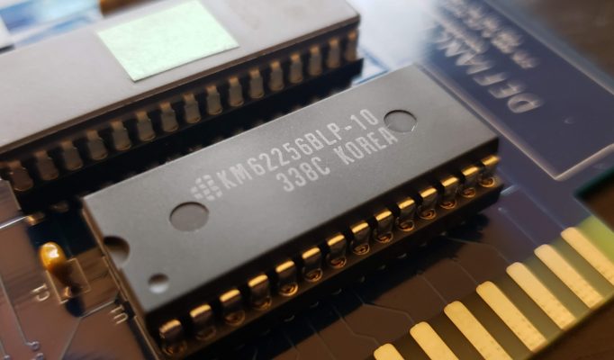
- 1) 62256BLP 32k byte Static RAM Chip. We use 27K of the 32 available.
- 1) 27C020 or 27C2001 256k byte EPROM Chip (I had the 27C020, but you might find the 27C2001 easier to find)
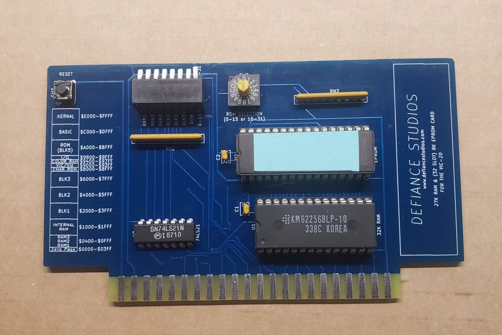
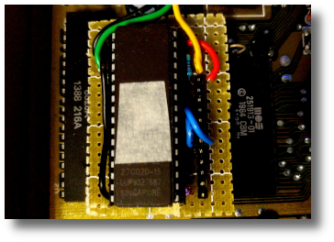
Here’s a photo of the cartridge. I used jclpcb.com to manufacture the board, here are the gerber files in .zip format if you want to have the board manufactured for your own cartridge.
Important!
There are some caveats with the cartridge.
Since this was a one-off for me I have no plans to update this card and the issues are small enough that I can live with them.
Both of the issues I have were caused by a difference between the schematic symbols in KiCad and the PC board footprint I chose for the board layout.
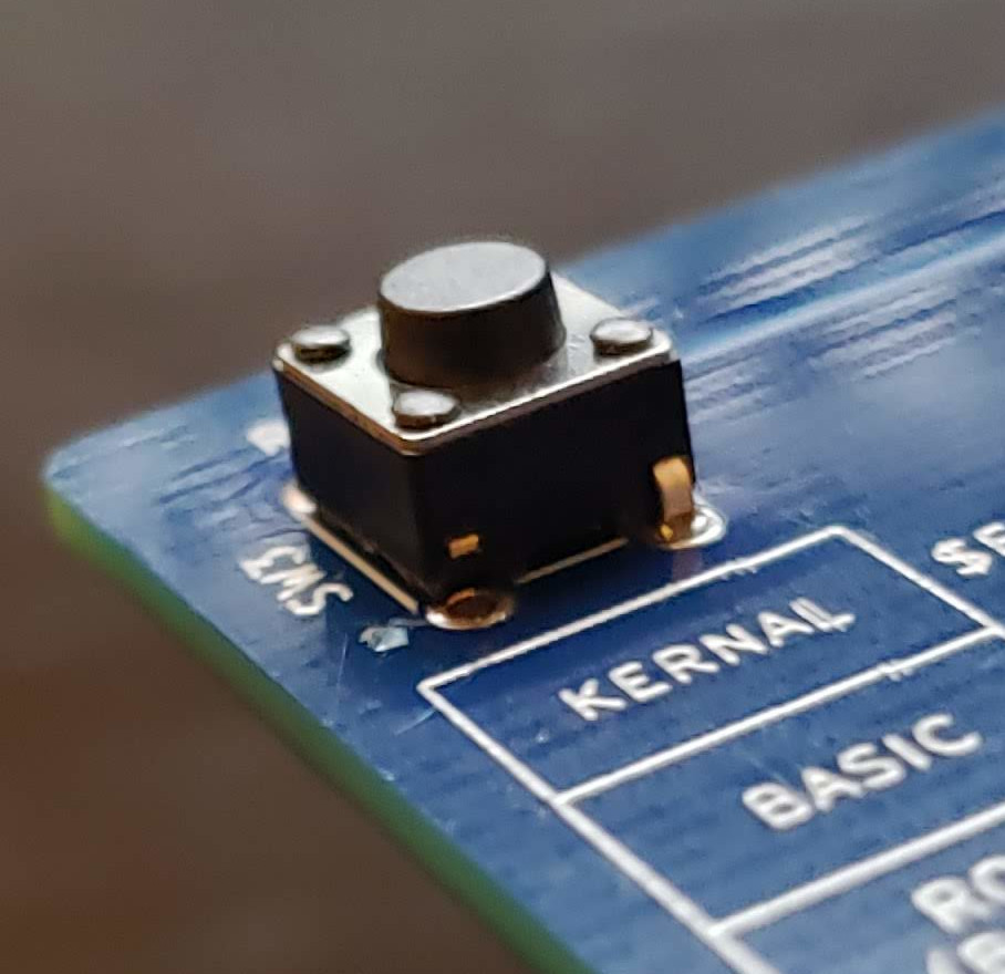
First is the reset button. On the schematic it all looks good, but on the cartridge, the way the four pins are wired would cause the reset line to be shorted constantly if all four leads on the button were soldered in. The solution was to just solder the opposite corners to the card and cut off the other two preventing a short between the pins. Test your button to confirm its pins and contacts. (As a side note, the reset switch isn’t required for the cartridge to run, it’s just so darn handy to have)
The second issue is the rotary dial. Again there was a discrepancy between the schematic and the footprint used. The result is that when you turn the dial clockwise, instead of the binary code increasing by 1, it increases by 4. So the output from the dial to the EPROM address input is 0,4,8,12,1,5,9,13,2,6,10,14,3,7,11,15. To compensate for this I had to program the EPROM based on this order. For example, if I wanted something to be available when the dial was set to 1, I would need to program the EPROM with the data starting at the 4th bank of 8k. With a little bit of planning this shouldn’t be a big deal.
The EPROM Programmer
I’m not going to go into a whole lot of detail about programming the EPROM. You’ll need an EPROM programmer of course. I have a TL866 MiniPro Universal programmer. I use Linux to program it on the command line, but if you use Windows, or Mac, there should be a GUI programmer application you can use.
The important thing is to remember that you are programming 8k blocks, or more specifically 8192 byte per block. If you have a program that is less than the 8192 byte, you’ll need to pad it. I use zeros, but any value will do. The other thing is that if you don’t have 32 programs to put on the EPROM chip, you’ll need to pad that as well until you fill the entire 262,144 bytes (256k) of data. If you don’t, the EPROM writing software will give you an error. Perhaps in another post I’ll go into more detail with programming.
Here is a 256k binary file I made to test the chip and the slots. Every 8k is labeled with a sequential number so when you PEEK(40960) on the VIC with the rom switch engaged, you can see what slot the computer sees on the EPROM chip. You can even write this little program to check the slots.
10 PRINT PEEK(40960)
20 GOTO 10
If you run this program and turn the rotary dial, it will tell you what EPROM slot you currently have access too. The last dip switch will select between for the first and last 16 slots of the chip.
One last thing about DIP switches
The dip switch is pretty self explanatory, but there is one thing to note. RAM 1, 2, and 3 refer to 1K blocks of RAM before the internal memory and BLOCKS 1, 2, and 3 refer to the three 8k ram blocks of memory after internal memory. Block 5 refers to the 8k section of memory usually reserved for ROM cartridges like games and utilities and does not show up as free BASIC RAM because it is not connected to the rest of the free RAM of the computer. There is some I/O and color memory positioned before it. It was one of the reasons I decided to not just make it a RAM expansion, but instead use it for and EPROM slot.
The other thing to note is that RAM 1, 2, and 3 are only visible to BASIC if just those three dip switches are on. Once you activate BLOCK 1, the 3k of extra RAM from the RAM 1, 2, and 3 disappear. This is because the VIC needs to move the screen memory to the start of internal RAM to make the 8k of additional memory to be continuous with the internal RAM. All BASIC RAM must be continuous and the screen memory can only be stored on internal RAM so you either have the 3k expansion before internal memory, or the 24k RAM expansion after the internal memory. The screen memory location moves for any upgrade 8k and above.
So if for some reason you wanted to do less that the full load of RAM, start with BLOCK 1 going up, or RAM 3 going down. Turning on just RAM 1 or 2 without any other RAM or Blocks on will result in a locked up VIC on bootup. Like wise, setting BLOCK 2 on without BLOCK 1 on will simply not be available to BASIC.
So hopefully I’ve given you enough information to build your own VIC-20 expansion card. The VIC is a capable little machine, especially if it has the memory to give you room to program it.
AL
Thanks for making this! I saw it on Adrian Black Digital Basement II.