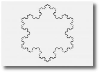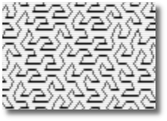
In the last post, I talked about how L-systems work and how you can make interesting images with repeating patterns using just a few small rules. This article will break down the BASIC program that makes it happen.
This program does use machine language to handle the drawing of the images once the computer goes through all the passes of the L-system. I use the Down & Dirty Graphics Wedge I created specifically for the purpose of playing with graphics on the C64 and sharing them easily. Line 1030 of this program does a quick check of upper RAM to see if the wedge is loaded and line 1040 will start the wedge.
1000 REM -- L-SYSTEM PROGRAM --
1010 REM -- DEFIANCE STUDIOS --
1020 REM ----------------------
1030 IFPEEK(49152)<>76THENPRINT"LOADING ML":LOAD"HIRES.PRG",8,1
1040 SYS49152:REM START GRAPHICS WEDGE
Next we need to reserve some memory for our string. The built in string variables in BASIC are limited to 255 characters. Our string will have a lot more, sometimes as much as 18K of ram. I needed to create my own workspace. Memory locations 55 and 56 point to the end of BASIC RAM. Normally, this is set to 40960 (the beginning of the BASIC language ROM). 55 is normally set to 0 and 56 is set to 160. Location 56 is the high byte of the 16 bit pair so you mulitply PEEK(56)*256+PEEK(55) to get the current top of BASIC RAM. I wanted to reserve 20K bytes of memory for the L-system. 20K is actually 20480 bytes. I divided that number by 256 and came up with 80. I then needed to subtract that from the current setting of 160 to get POKE56,80. I then needed to do a CLS to clear the pointers in BASIC so it knows how much memory it now has available to it. This is especially important for BASIC string variables as they are stored at the end of BASIC RAM and work their way downward toward the program.
Line 1060 sets S to the start of the stack for our reserved memory space. 1070 declares our graphics variables which need to be set for the graphics wedge.
1050 POKE56,80:CLR:REM MAKE 20K SWAP
1060 S=20480:REM START OF STACK SPACE
1070 X%=0:Y%=0:Z%=0:C%=1
1080 :
Lines 1090 to 1270 are explained in more detail in the previous article. These are meant to be modified by the user to create their own L-system images.
1090 REM -----  SETUP ARGUMENTS  -----
1100 REM ----- CHANGE THESE VARS -----
1110 SB=1    :REM SCREEN BORDER COLOR
1120 SS=1    :REM SCREEN COLOR
1130 SL=0    :REM LINE/CHARACTER COLOR
1140 Z=4     :REM NUMBER OF PASSES
1150 X=0     :REM START X POSITION
1160 Y=0     :REM START Y POSITION
1170 A=0     :REM START ANGLE
1180 AT=2    :REM ANGLE TYPE 1,2, OR 3
1190 :       :REM 1=90, 2=60, 3=120
1200 LX=319  :REM INITIAL WIDTH
1210 LY=199  :REM INITIAL HEIGHT
1220 LD=3    :REM LENGTH DIVISOR
1230 N$=""   :REM SYSTEM NAME
1240 I$=""   :REM INITIAL STATE
1250 F$=""   :REM RULE 1
1260 G$=""   :REM RULE 2
1270 REM -----------------------------
1280 :
Now that our L-system variables are set, we want to do some setup. Specifically, we want to convert I$, F$, and G$ into number values. The reason for this is that BASIC is slow enough without having to do a bunch of string manipulations multiple times while processing the rules. Here we convert the stings to a series of bytes that represent the rules. We store these bytes at the beginning of the stack and move the stack pointer forward to keep this data protected. The variable F0 and G0 store the starting address for each rule and F1 and G1 store the length of each rule. These will be used later when we run the rules.
Lines 1320-1370 process the F rule. Line 1380 checks to see if there is a G rule and bypasses processing it if not. Lines 1400-1450 process the G rule.
1290 REM ------ SOME SETUP WORK ------
1300 REM -- BREAKUP F RULE TO PARTS --
1310 F1=LEN(F$):G1=LEN(G$)
1320 F0=S
1330 FORN=1TOF1
1340 : POKES,ASC(MID$(F$,N,1))
1350 : S=S+1
1360 : NEXTN
1370 F1=F1-1
1380 IFG1=0THEN1470:REM SKIP IF NO G
1390 REM -- BREAKUP G RULE TO PARTS --
1400 G0=S
1410 FORN=1TOG1
1420 : POKES,ASC(MID$(G$,N,1))
1430 : S=S+1
1440 : NEXTN
1450 G1=G1-1
The next few lines now process I$ and place it directly on the stack to be processed. Line 1470 assigns T1 to the start of the stack. This program has two variables, T1, T2, which represent track1 and track2 stacks used by the L-system. Track1 always has a completed string where track2 is always building the new string during a pass. Basically the computer looks at data from track 1, processes the rules and creates a new string in track 2. That is why after each pass, there is a “moving stack” routine that needs to run. This copies the newly created string in track2 back into track 1 for the next pass. Lines 1480-1510 place the initial position on the stack and creates an end variable called C1 marking the end of the track1.
1460 REM -PLACE INITIAL POS ON STACK-
1470 T1=S
1480 FORN=1TOLEN(I$)
1490 : POKET1+N-1,ASC(MID$(I$,N,1))
1500 : NEXTN
1510 C1=LEN(I$)-1
Finally, we set some colors based on the variables set by the user, and we’re ready to run the L-system.
1520 REM -- SET SOME COLORS AND GO --
1530 POKE53280,SB:POKE53281,SS
1540 POKE646,SL:PRINTCHR$(147);
1550 C%=SL*16+SS:REM GRAPHIC SCRN COLR
1560 T1=S:PRINT"{RVS}"N$
Now we are at the L-system engine itself. If you looked at the previous article, you know that the process is pretty simple. Go through the string and replace variable within the string with a new string of variables based on rules. Then repeat for however many passes you want. The code from 1580 to 1700 does just that.
Line 1580 starts a FOR/NEXT loop that runs the code through the number of passes designated by the Z variable in the program. 1600 clears the counter for the track2 stack and then calculates the new starting point for the track2 stack which is after the end of the track1 stack plus a 2 byte buffer. Line 1610 updates the length of the lines to be drawn in the drawing routine later, once all the passes are done.
1570 REM ----- RUN THE L-SYSTEM -----
1580 FORI=1TOZ
1590 : PRINT"{RVS}PASS"I"{LEFT} OF"Z
1600 : C2=0:T2=T1+C1+2
1610 : LX=LX/LD:LY=LY/LD
Line 1620 starts the nested loop that goes through the stack storing the string in track1. It peeks at the location, then compares it with the PETSCII codes for F (70) and G (71). If it hits either of those two characters, it GOSUBs to the appropriate subroutine, and on return, bypasses the rest of the code by jumping to the NEXT statement at 1680 to go to the next item in the stack.
If neither of those conditions are met, then the program passes down to line 1670 where it simply copies the current character (either a + or -) and places it in the new string. Then at line 1680, it goes to the next step in the FOR/NEXT loop.
Once it gets through the entire stack for this pass, it goes to a subroutine to copy the new track2 stack into the track1 stack. The line 1690 does this, but only if we have not finished processing all the passes. No need to copy the stack the last time, we’ll just draw the image using the data in the track2 stack. Line 1720 goes to the drawing routine.
1620 : FORN=0TOC1
1630 :   IFC2+T2>40959THENPRINT:PRINT"STACK OVERFLOW ERROR":STOP
1640 :   TT=PEEK(T1+N)
1650 :   IFTT=70THENGOSUB1730:GOTO1680
1660 :   IFTT=71THENGOSUB1790:GOTO1680
1670 :   POKET2+C2,TT:C2=C2+1
1680 :   NEXTN
1690 : IFI<ZTHENGOSUB1850:REM MOVE STACK
1700 : NEXTI
1710 I=Z
1720 GOTO1920:REM DRAW CURVE
The next two sections of code run the F and G rules. Basically the code just copies the rule and places it in the string in track2 in place of the F or G in found int track1. For the F rule, F0 = the start of the rule in memory, F1 = the length of the rule, and C2 is the pointer for track2 stack. Likewise for the G rule, G0 = start of rule in memory, G1 = length of the rule.
1730 REM -------- RUN F RULE --------
1740 PRINT"F";
1750 FORRL=0TOF1
1760 : POKET2+C2,PEEK(F0+RL):C2=C2+1
1770 : NEXTRL
1780 RETURN
1790 REM -------- RUN G RULE --------
1800 PRINT"G";
1810 FORRL=0TOG1
1820 : POKET2+C2,PEEK(G0+RL):C2=C2+1
1830 : NEXTRL
1840 RETURNThe next routine copies the track2 stack into track1. Then in line 1900 a new length for track1 is calculated and stored in C1 for the next pass.
1850 REM ------- MOVE  MEMORY -------
1860 PRINT:PRINT"MOVING STACK":PRINT
1870 FORQ=0TOC2
1880 : POKET1+Q,PEEK(T2+Q)
1890 : NEXTQ
1900 C1=C2-1
1910 RETURN
So all that’s left is to draw the picture on the graphics screen. This uses my Down & Dirty Graphics Wedge. Commands preceding with a left arrow (←) are part of the wedge commands. I encourage you to check out the post on how the wedge works.
The first few lines, 1930 to 1960 set up the screen and set some variables for drawing. Line 1940 sets the bitmap colors, clears the screen, and turns on the bitmap graphics mode. Line 1950 set the variables X% and Y% to equal our initial X and Y coordinates set earlier. X% and Y% communicate directly with the graphics wedge.
Finally, there is an ON GOSUB command that is used throughout the drawing routine to manage the current drawing angle. Here it sets up the initial angle as set in the variables earlier in the code.
1920 REM -------- DRAW CURVE --------
1930 PRINT:PRINT"DRAW IMAGE"
1940 ←L:←C:←G
1950 X%=X:Y%=Y:←P
1960 ONATGOSUB2130,2260,2260
Lines 1970 through 2080 run a FOR/NEXT loop through all of the track2 stack. Line 1980 peeks into the current memory location and saves the value as D. Then D is checked to see if it is less than 70. 70 is the PETSCII value for F so anything below F will need to be processed differently. Lines 2000 – 2050 assume that since D is 70 or above that the character is an F or a G and the rules for each state to draw the line forward.
Line 2000 increments X and Y by DX and DY respectively. We’ll talk about DX and DY shortly. This command moves the position of X and Y to the next draw to position and then assigns those values to X% and Y% which are used by the graphics wedge.
Lines 2010 through 2040 check to make sure X% and Y% stay on the screen. The graphics wedge will throw out an illegal quantity error if these variables go outside the screen size of 319×199.
Line 2050 executes a draw to command in the graphics wedge that draws a line from the previous point to this new point at X%,Y%. Finally line 2060 skips over the the next line which deals with processing turns and goes to the NEXT N statement to move forward to the next character in the string.
1970 FORN=0TOC2-1
1980 : D=PEEK(T2+N)
1990 : IFD<70THEN2070:REM SKIP LINE
2000 :  X=X+DX:Y=Y+DY:X%=X:Y%=Y
2010 :  IFX%<0THENX%=0
2020 :  IFY%<0THENY%=0
2030 :  IFX%>319THENX%=319
2040 :  IFY%>199THENY%=199
2050 :::←D
2060 :  GOTO2080
Line 2070 is for processing the + and – character of the string.
The variable used in the ON GOSUB statement references what kind of angles the + and – represent as set by the user in line 1180. The program then executes the code at the respective GOSUB locations.
1180 AT=2    :REM ANGLE TYPE 1,2, OR 3
1190 :       :REM 1=90, 2=60, 3=120
2070 : ONATGOSUB 2100,2180,2220
2080 : NEXTN
2090 GOTO2340:REM DONE DRAWINGThe ON GOSUB command goes to the next three routines. They all work the same. For 90 degree turns, when D = 43, A is increased by 90. 43 is the PETSCII code for “+”. Likewise, 45 (PETSCII for “-“) will cause 90 to be subtracted from A. Also in lines 2110 and 2120, there is a check to make sure A stays within 0 and 359 degrees. The program will just wrap A around when needed.
The next 4 IF statements then set of variables DX and DY. Earlier in the program if an F or G were present, the program would add DX to X and DY to Y. DX and DY represent a vector here and represent how long and what direction the point will be from the previous point. LX and LY were calculated while the L-system was working through its multiple passes earlier. The IF statements simply take LX and LY and set them to positive or negative in DX and DY or make them zero depending on the current angle direction.
2100 REM ------ 90 DEGREE TURN ------
2110 IFD=43THENA=A+90:IFA>270THENA=0
2120 IFD=45THENA=A-90:IFA<0THENA=270
2130 IFA=0THENDX=LX:DY=0
2140 IFA=90THENDX=0:DY=LY
2150 IFA=180THENDX=-LX:DY=0
2160 IFA=270THENDX=0:DY=-LY
2170 RETURN
Lines 2190-2210 handle A when the system is set to 60 degrees. It does the same thing lines 2110 and 2120 did for 90 degrees above. Then, in line 2210, the program jumps down into the 120 degree turn code because 60 degrees and 120 degrees will share the same angles for calculation the vector.
2180 REM ------ 60 DEGREE TURN ------
2190 IFD=43THENA=A+60:IFA>300THENA=0
2200 IFD=45THENA=A-60:IFA<0THENA=300
2210 GOTO2250
For 120 degrees, lines 2230 and 2240 handle the angle calculation. The program then drops down to the section of code used by both 60 and 120 degrees. Lines 2260-2310 work the same way lines 2130-2160 did for 90 degrees. For the angles that aren’t 0 and 180, LX is divided by two for the upward and downward angles.
2220 REM ----- 120 DEGREE TURN  -----
2230 IFD=43THENA=A+120:IFA>300THENA=A-360
2240 IFD=45THENA=A-120:IFA<0THENA=A+360
2250 REM ---- A SETS FOR 120/60  ----
2260 IFA=0THENDX=LX:DY=0
2270 IFA=60THENDX=LX/2:DY=LY
2280 IFA=120THENDX=-LX/2:DY=LY
2290 IFA=180THENDX=-LX:DY=0
2300 IFA=240THENDX=-LX/2:DY=-LY
2310 IFA=300THENDX=LX/2:DY=-LY
2320 RETURN
All of these subroutines are then returned to the main drawing loop until it has processed the entire stack where it then jumps down to here to wait for a key-press to bring the text screen back and exit the program.
2340 REM ------ END OF PROGRAM ------
2350 POKE198,0:WAIT198,1:POKE198,0
2360 ←T
2370 END
Since this program is a template, there are sections of code that will never get used depending on how you set your variables. I hope this makes it clear how the program works.
Often when I do these projects in BASIC, they are proof of concept models for trying things out in machine language. I may do that here, but I also honestly enjoy writing these programs in BASIC, even if they are slow to process.
-M