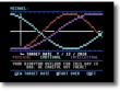
In the last post, I introduced a utility that used PETSCII graphics characters to make a pseudo bitmap screen using the normal C64 text screen. In this post, I’ll discuss the process of programming the utility and why I made the choices that I did.
So, for a recap, I was looking to make a utility that had filled the following criteria:
- It needed to give me the ability to plot a point, remove a point, and check to see if a point was already plotted.
- It needed to use a simple X, Y coordinate system to plot the points.
- It needed to have color easily controlled.
- It needed to only use the built in BASIC commands without alteration so that it could be compiled.
- It needed to check to make sure if X or Y was out of range, and would stop execution of the BASIC program with an ILLEGAL QUANTITY error.
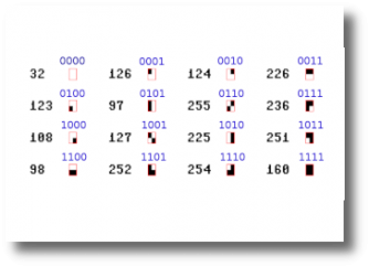
First things first, I needed to collect and organize the PETSCII characters needed to build the utility. It turns out that a total of 16 graphic characters are needed for the task, which makes sense because each block is 1/4 the size of a full character. With 4 unique positions in a character, it is equivalent to a 4 bit number. Since I observed that relationship, I figured that each lone block would represent one of the digits of the 4 bit number and all other combination would logically fall into place. Look at the chart of characters. To the left of each symbol is the screen code (in decimal) for each of the characters and above is my binary representation of the character. 0001, 0010, 0100, and 1000 represent the four corner block characters. So if you were plotting a block, the computer would figure out what was in the location by peeking into it and then use an ORA statement to combine what was there with what you were adding.
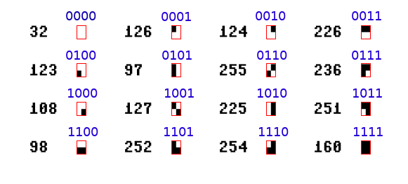
For example, if it turned out that your plotted point ended up being the bottom right block of the character (1000), and the location already happen to have the a top left block character in it (0001), the computer would ORA them together to get the checker character (1001). The computer would then overwrite the old screen code (126) with the new one (127) using a lookup table. On the screen it would simply look like a small block was added where you wanted it.
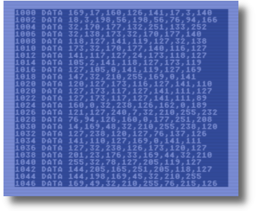
Before we get to that point, there is a bunch of work needed to determine where on the screen we need for the location plotted. Here’s a breakdown of the program as written in Turbo Macro Pro (you can download the full listing here):
At the end of the program are some working variables and the lookup tables.
               ;WORKING MEMORY
CFD3 00        XPOS     .BYTE $00
CFD4 00        YPOS     .BYTE $00
CFD5 00        COLOR    .BYTE $00
CFD6 00        RTURN    .BYTE $00
CFD7 00 00     SBYTE    .BYTE $00,$00
CFD9 00        XTEMP    .BYTE $00
CFDA 00 00     YTEMP    .BYTE $00,$00
CFDC 00 00     YTEMP2   .BYTE $00,$00
CFDE 00        NEWNIB   .BYTE $00
CFDF 00        POINT    .BYTE $00
XPOS, YPOS, and COLOR are the memory locations you POKE data into for plotting points in CPLOT. RTURN is the location you PEEK into when seeing if a point is already occupied. The rest of the variables from $CFD7 to $CFDF are working variable for the ML program to use.
               ;CHARACTER AND POSITION POSITION LOOKUP
CFE0 20 7E 7C E2
               CHAR     .BYTE $20,$7E,$7C,$E2
CFE4 7B 61 FF EC
                        .BYTE $7B,$61,$FF,$EC
CFE8 6C 7F E1 FB
                        .BYTE $6C,$7F,$E1,$FB
CFEC 62 FC FE A0
                        .BYTE $62,$FC,$FE,$A0
$CFE0 to $CFEF (called CHAR) is the lookup table for the screen codes used to make the blocks on the screen. The values line up with the diagram at the top showing the characters used for the program. Finally $CFF0 to $CFF3 (called QLOOKUP) is a lookup table to help determine which corner of the character is to be plotted and corresponds to the CHAR lookup table above it.
CFF0 01 02 04 08
               QLOOKUP  .BYTE $01,$02,$04,$08
CFF4 4D 2E 43 41 53 53 45 52 41
                        .TEXT "M.CASSERA"
                        .END
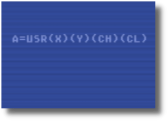
Above the working memory and lookup tables are my jump tables. This is where you would initiate one of the three commands CPLOT has. $CF9E (SYS53150) sets a point, $CFAD (SYS53165) resets a point, and $CFC3 (SYS53187) checks a point to see if it’s already occupied. From there the program jumps to common subroutines shared by all with some other commands added to RSETP and CPOINT.
CF9E 20 D4 CE  SETP     JSR GETBYTE
CFA1 20 58 CF           JSR LOGIC
CFA4 20 8D CF           JSR GETCHAR
CFA7 20 91 CF           JSR PUTDOT
CFAA 4C 95 CF           JMP GCOLOR

CFAD 20 D4 CE  RSETP    JSR GETBYTE
CFB0 20 58 CF           JSR LOGIC
CFB3 38                 SEC
CFB4 A9 0F              LDA #$0F
CFB6 ED DE CF           SBC NEWNIB
CFB9 2D DF CF           AND POINT
CFBC AA                 TAX
CFBD 20 8D CF           JSR GETCHAR
CFC0 4C 91 CF           JMP PUTDOT

CFC3 20 D4 CE  CPOINT   JSR GETBYTE
CFC6 20 58 CF           JSR LOGIC
CFC9 AD DE CF           LDA NEWNIB
CFCC 2D DF CF           AND POINT
CFCF 8D D6 CF           STA RTURN
CFD2 60                 RTS
GETBYTE
The first thing that needs to be done is to read the X, Y coordinates poked into memory, make sure they are not out of range and run them through a formula to determine the memory location of corresponding C64 text screen. The formula if written in BASIC would look like:
X = 0 to 79
Y = 0 to 49
screen position = 1024+INT(X/2)+(INT(Y/2)*40)
This is the first section of GETBYTE. It starts by clearing the decimal and carry flags and clearing some temp variables.
CED4 D8        GETBYTE  CLD
CED5 18                 CLC
CED6 A9 00              LDA #$00
CED8 8D DD CF           STA YTEMP2+1
CEDB 8D DB CF           STA YTEMP+1
Then it’s going to shift both the values for X and Y to the right one bit effectively dividing them by two with no remainders. While it does this, it checks to make sure the X and Y values are within safe numbers. For example, $CEDE loads the X value into the accumulator and compares it with $50 (decimal 80). If it is less than $50, then it will Branch on Carry Clear (BCC) to SAFEX. If not, it will drop down to $CEE5 where it loads the x register with $0E, which is the code for Illegal Quantity Error in BASIC and then jumps to $A437, which is BASIC’s General Error Handler routine. This will halt the BASIC program and generate the error along with BASIC program line it was generated. If X is ok, then it will do the same thing for Y. Note that the value of X/2 is stored in XTEMP and Y/2 is stored in YTEMP and YTEMP2.
                        ;INT(X/2)  INT(Y/2)
CEDE AD D3 CF           LDA XPOS   ;XPOSITION
CEE1 C9 50              CMP #$50   ;TOO HIGH? >79
CEE3 90 05              BCC SAFEX  ;NO - CONTINUE
CEE5 A2 0E              LDX #$0E   ;ILLEGAL QUANTITY
CEE7 4C 37 A4           JMP $A437  ;JUMP TO ERROR
CEEA 4A        SAFEX    LSR A      ;/2
CEEB 8D D9 CF           STA XTEMP  ;STORE TEMP
CEEE 18                 CLC
CEEF AD D4 CF           LDA YPOS   ;Y POSITION
CEF2 C9 32              CMP #$32   ;TOO HIGH? >49
CEF4 90 05              BCC SAFEY  ;NO - CONTINUE
CEF6 A2 0E              LDX #$0E   ;ILLEGAL QUANTITY
CEF8 4C 37 A4           JMP $A437  ;JEMP TO ERROR
CEFB 4A        SAFEY    LSR A      ;/2
CEFC 8D DA CF           STA YTEMP
CEFF 8D DC CF           STA YTEMP2
Now we need to do some multiplication. The formula calls for Y/2 (now stored in YTEMP and YTEMP2) to be multiplied by 40. We do this by shifting the bits of YTEMP to the left. Because 40 doesn’t neatly fit into multiples of 2, I had to break the formula down so that it did. Here is the altered formula:
(INT(x/2)+INT(Y/2)*32+INT(Y/2)*8)
Using the program variables:
XTEMP + YTEMP*32+YTEMP2*8
32 is 2^5 and 8 is 2^3, so we create two loops, one for 8 iterations, the other for 3. We then add the results of the two loops to give us the final Y/240 result which will get added to X/2. Here is the loop for YTEMP32.
CF02 A2 05              LDX #$05   ;MULT *32
CF04 18        LOOP1    CLC
CF05 2E DA CF           ROL YTEMP      ;*2
CF08 2E DB CF           ROL YTEMP+$01  ;*2
CF0B CA                 DEX
CF0C D0 F6              BNE LOOP1
Here is the loop for YTEMP2*8.
CF0E A2 03              LDX #$03   ;MULT *8
CF10 18        LOOP2    CLC
CF11 2E DC CF           ROL YTEMP2     ;*2
CF14 2E DD CF           ROL YTEMP2+$01 ;*2
CF17 CA                 DEX
CF18 D0 F6              BNE LOOP2
Since these numbers are going to be greater than 255, a high byte was added to store it. Notice that the carry bit is cleared at the beginning of each iteration of the loop, but not cleared between to ROL statements. That is so if a bit from YTEMP or YTEMP2 is shifted past the 7th bit, it will carry over to the 0th bit of the high byte of the number.
Next we add YTEMP and YTEMP2 together and re-store the value into YTEMP. Remember to clear the carry bit before doing the addition.
CF1A 18                 CLC
CF1B AD DA CF           LDA YTEMP  ;ADD TWO RESULTS
CF1E 6D DC CF           ADC YTEMP2 ;TOGETHER
CF21 8D DA CF           STA YTEMP
CF24 AD DB CF           LDA YTEMP+$01
CF27 6D DD CF           ADC YTEMP2+$01
CF2A 8D DB CF           STA YTEMP+$01
Now we add XTEMP and YTEMP together and store the result in a few locations that will alter a later section of the program.
CF2D 18                 CLC           ;GET LOOKUP LOC
CF2E AD D9 CF           LDA XTEMP
CF31 6D DA CF           ADC YTEMP
CF34 8D 79 CF           STA LOOKUP+$01
CF37 8D 92 CF           STA PUTDOT+$01
CF3A 8D 9B CF           STA PUTCOL+$01
CF3D AD DB CF           LDA YTEMP+$01
CF40 69 00              ADC #$00
CF42 8D DB CF           STA YTEMP+$01
LOOKUP, PUTDOT, and PUTCOL are all located in different parts of the program. These STA commands are altering the ML code so those routines either look into or place into specific memory locations, specifically in the low byte location. Next in the program, the high byte location will be altered.
                        ;ADD $0400 FOR SCREEN MEM
CF45 18                 CLC
CF46 AD DB CF           LDA YTEMP+$01
CF49 69 04              ADC #$04
CF4B 8D 7A CF           STA LOOKUP+$02
CF4E 8D 93 CF           STA PUTDOT+$02
CF51 18                 CLC
CF52 69 D4              ADC #$D4       ;ADD FOR COLOR
CF54 8D 9C CF           STA PUTCOL+$02
CF57 60                 RTS
This section of code adds $04 to the high byte (for screen memory $0400) and then $D4 (for color memory $D800). $D4 is used instead of $D8 because the accumulator already had $04 added to it. The results are stored 2 bytes after LOOKUP, PUTDOT, and PUTCOL. We now know the screen byte and color byte that needs to be manipulated for CPLOT to plot the X,Y coordinate entered.
LOGIC
Up to this point, we’ve checked to make sure our X and Y values are legal, and we’ve determined the location on the C64 screen we are dealing with. The next step is to figure out what character we need to use to draw the proper block on the screen. There are a couple of things that need to be done to do this. The first is to determine which of the four blocks available to us needs to be used. First thing I did was determine if X and Y were odd or even. This is done with and AND #$01 command. For Y, I also did a ROL A command to shift the result to the left one bit and then added it to the result of X. This gave me a value between 0 and 3 for the block position. 0 is the top-left block, 1 is the top-right, 2 is the bottom-left and 3 is the bottom-right.
CF58 18        LOGIC    CLC            ;GET BITS
CF59 AD D3 CF           LDA XPOS
CF5C 29 01              AND #$01
CF5E 8D D9 CF           STA XTEMP
CF61 18                 CLC
CF62 AD D4 CF           LDA YPOS
CF65 29 01              AND #$01
CF67 2A                 ROL A
CF68 18                 CLC
CF69 6D D9 CF           ADC XTEMP      ;ADD THEM UP
Next, I transfer the result to the x register and do a lookup to get the proper binary nibble that corresponds to the table at the top.
CF6C AA                 TAX
CF6D BD F0 CF           LDA QLOOKUP,X  ;LOOKUP BIT
CF70 8D DE CF           STA NEWNIB     ;STORE BIT
CFF0 01 02 04 08
               QLOOKUP  .BYTE $01,$02,$04,$08
The program then determines what character is already occupying the memory location on the screen that we need to update. It does this by going through all sixteen possible characters and comparing it the memory location.
CF73 A2 00              LDX #$00
CF75 BD E0 CF  LOOP3    LDA CHAR,X     ;GET CURRENT
CF78 CD 00 04  LOOKUP   CMP $0400      ;FIGURE OUT
CF7B F0 07              BEQ SKIP       ;WHAT IT IS
CF7D E8                 INX
CF7E E0 10              CPX #$10
CF80 D0 F3              BNE LOOP3
CF82 A2 00              LDX #$00
               SKIP
The X register simply counts up from zero until the character in the lookup table matches the character on the screen. Once the values match, the loop breaks out at line CF7B to ‘SKIP’. If not, the program continues to loop until it has gone through all the character in the lookup table. If it doesn’t find a match, then it assumes the character is a space character and moves on. It does this by counting up to $10 (the lookup table only goes to $0F), resets X to zero and moves on. The result is that if the location is occupied by anything other than black character, it will just get written over with a new block character.
Line CF78 is one of the lines that was altered in the code earlier so that instead of the accumulator being compared to $0400 as it is listed here, it will compare the accumulator to the value that was inserted into the memory locations held by the $0400. $0400 is simply the first location of screen memory and a place holder in the code.
CF84 8A                 TXA          ;TRANSFER TO .
CF85 8D DF CF           STA POINT
CF88 0D DE CF           ORA NEWNIB  ;OR WITH NEW
CF8B AA                 TAX
CF8C 60                 RTS
The program then transfers the X register , which is holding the current character information (via the lookup table) from the screen to the accumulator where it stores in in POINT for lookup purposes and then does an ORA statement with NEWNIB which is the new character information (also via the lookup table) to generate a new character code. It then transfers it back to the X register to be used elsewhere.
GETCHAR, PUTDOT, GCOLOR, PUTCOL
Finally, a few small routines the finish things up. GETCHAR simply gets the PETSCII block character from the lookup table with the X index. PUTDOT stores write a new character on the screen, the accumulator at this point will have the correct PETCII character stored in it. Also note that line $CF91 also has the $0400 place marker in it to be altered by the program elsewhere.
CF8D BD E0 CF  GETCHAR  LDA CHAR,X
CF90 60                 RTS

CF91 8D 00 04  PUTDOT   STA $0400      ;NEW CHAR
CF94 60                 RTS
CF95 AD D5 CF  GCOLOR   LDA COLOR
CF98 29 0F              AND #$0F
CF9A 8D 00 D8  PUTCOL   STA $D800      ;NEW COLOR
CF9D 60                 RTS
GCOLOR looks up the color setting poked into it in basic, does an AND command with $0F to ensure it is one of the 16 colors available and then stores it on the C64 color map. Line CF9A uses the place holder $D800 (the start of color memory). This also gets changed by the program to match the same location that a dot is getting placed.
Conclusion
This was a good and useful project to put together. This project really got me started at looking inside the C64 Kernal and seeing how I can use parts of it in my own programs. It also helped me sharpen up my math skills within assembly language. The key is breaking down multiplication and division problems into bit shifting algorithms. I’m thinking about building a similar utility using the hi-res/multi color screens the same way. Much like Simons’ Basic except I would continue to use standard BASIC commands so that the BASIC programs could still be compiled.
I hope whoever downloads this utility it finds it useful, and I hope this breakdown of how I programmed it is useful to people as well.
Michael